Extrinsic using measuring tape
This method requires us to center all cameras on a single vertical line in their views, optimally on the same spot. This vertical line can be either wardrobe edge or a piece of paper with line drawn over it and attached to a chair. Once we have our vertical line we need to measure following:
- Distances between each camera lens to the point they're looking at
- Distances from each device lens to next device in the chain
- Distance to the ground from camera lens of each device
- Distance to the ground of the points on the vertical line itself ( that's why we optimally align on a single spot so we have less to measure but that's not always possible )
On this page we will showcase a stereo calibration ( 2 devices ), but for the sake of completeness if we had 4 devices ( Device A,B,C,D ) we would perform measurements for pairs:
- Pair A - B
- Pair B - C
- Pair C - D
Navigate to Recording tab and enable each device that you want to calibrate. Order the devices appropriately using the arrow buttons. In examples on this page we identify our origin device as PS3: 0 and device to the right in the chain is Windows Media Foundation: Logitech C270.
Switch Recording Type to either Live Intrinsic or Live Extrinsic mode, we are going to use the cross-hair that will be visible during preview in either of these modes.
Select Resolution that is shared by all devices, resolution set here will determine allowed resolutions during animation recording. This example calibrates with 640x480 resolution and we will be allowed to record in that format only.
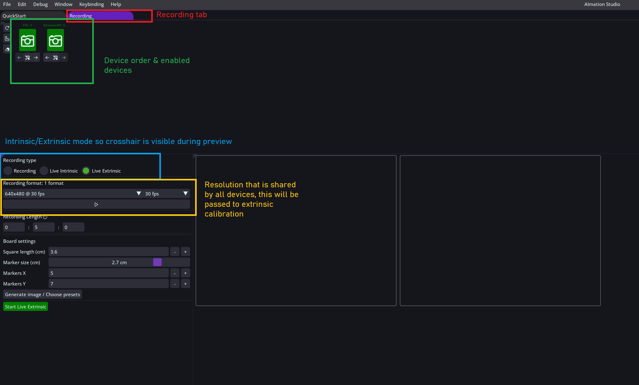
Once all devices are ordered and enabled, start preview by clicking on the play button below resolution field ( golden border on the image above ).
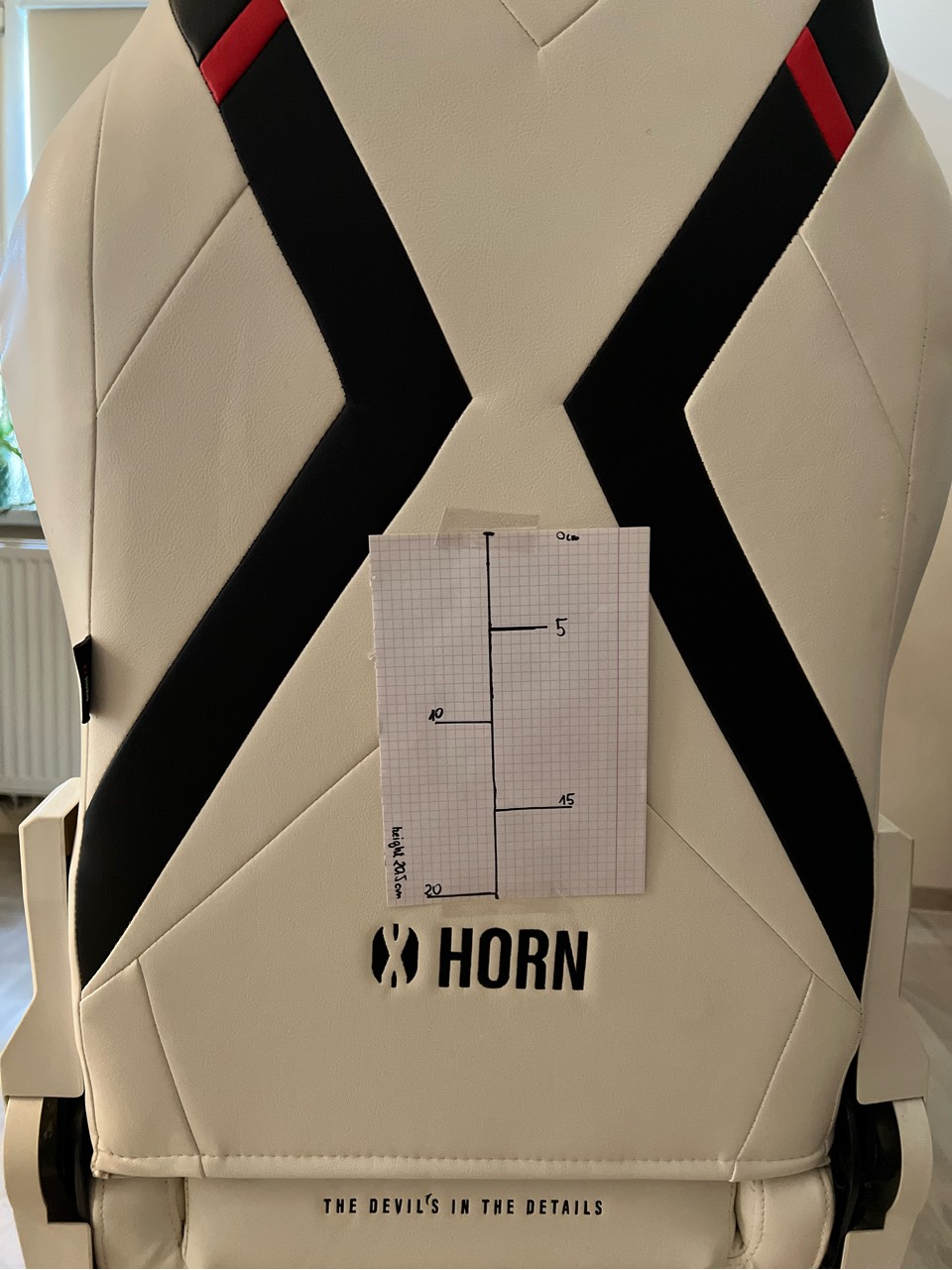
In this example we create a vertical line on a piece of paper and mark a spot every 5cm, we will attach this to a chair and align our device views on that line.
At this point we take our first measurement and it is from the very top of our paper to the ground, in our case it is 88cm. We do not measure at every step because it is a matter of basic math.
It is now time to actually place and align the devices, but before we do that just to re-iterate, extrinsic calibration is tied to the placement of the devices in the world, thus if position or orientation changes than calibration file is invalid and triangulation results will also be invalid. That means in scenarios where your setup is not permanent, it is recommended to physically mark exact final position of each device and of the vertical line itself ( if its moveable like in our case the chair ). If you do so, you can later align devices on the vertical line again and just load old extrinsic calibration file. There are many ways to achieve this, we do this by taking a picture of each device while making sure something as reference is in the background.
In case of placement on a desk or a place which usually vibrates when it is used, make sure to properly hold the devices in place, duct tape works great as always.
Place the devices, preferably on the same height, and align them on the line, preferably looking on the same spot but not necessary, in the example image below each camera is looking at different point, it is important they're on the same vertical line. Make sure that the devices are not rotated around their principal axis, the "up" direction on the image is exactly "up" in the world.
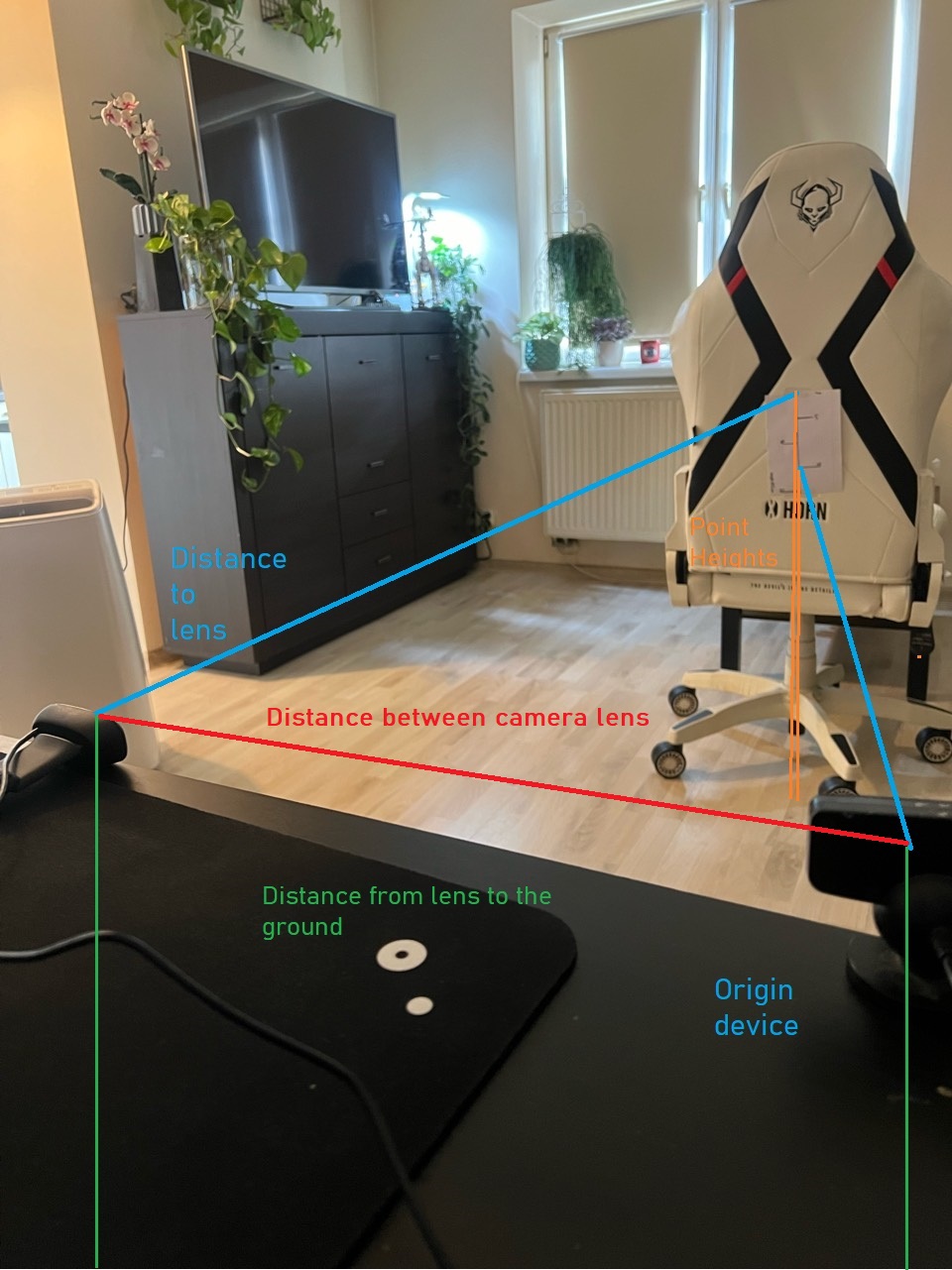
Once aligned, begin taking required measurements. It is recommended to start with heights of all devices and heights of each point on the vertical line then move on to distances between cameras and points. See two images below for image reference.
- Measure height from camera well (*) to the ground of each device
- For each device measure from the point on the vertical line that the camera is looking at to the ground. If you have evenly spaced points like in the example, you can calculate that now.
- In the same order as camera order, measure distances from lens to lens of each pair in the chain. Again, if we had a 4 device setup, we would have 3 pairs so 3 different measurements.
Usually accessing lens directly is not possible so roughly estimate by measuring to the well (*) or slightly above the device - Lastly for each device measure the distance to the point they're looking at on vertical line
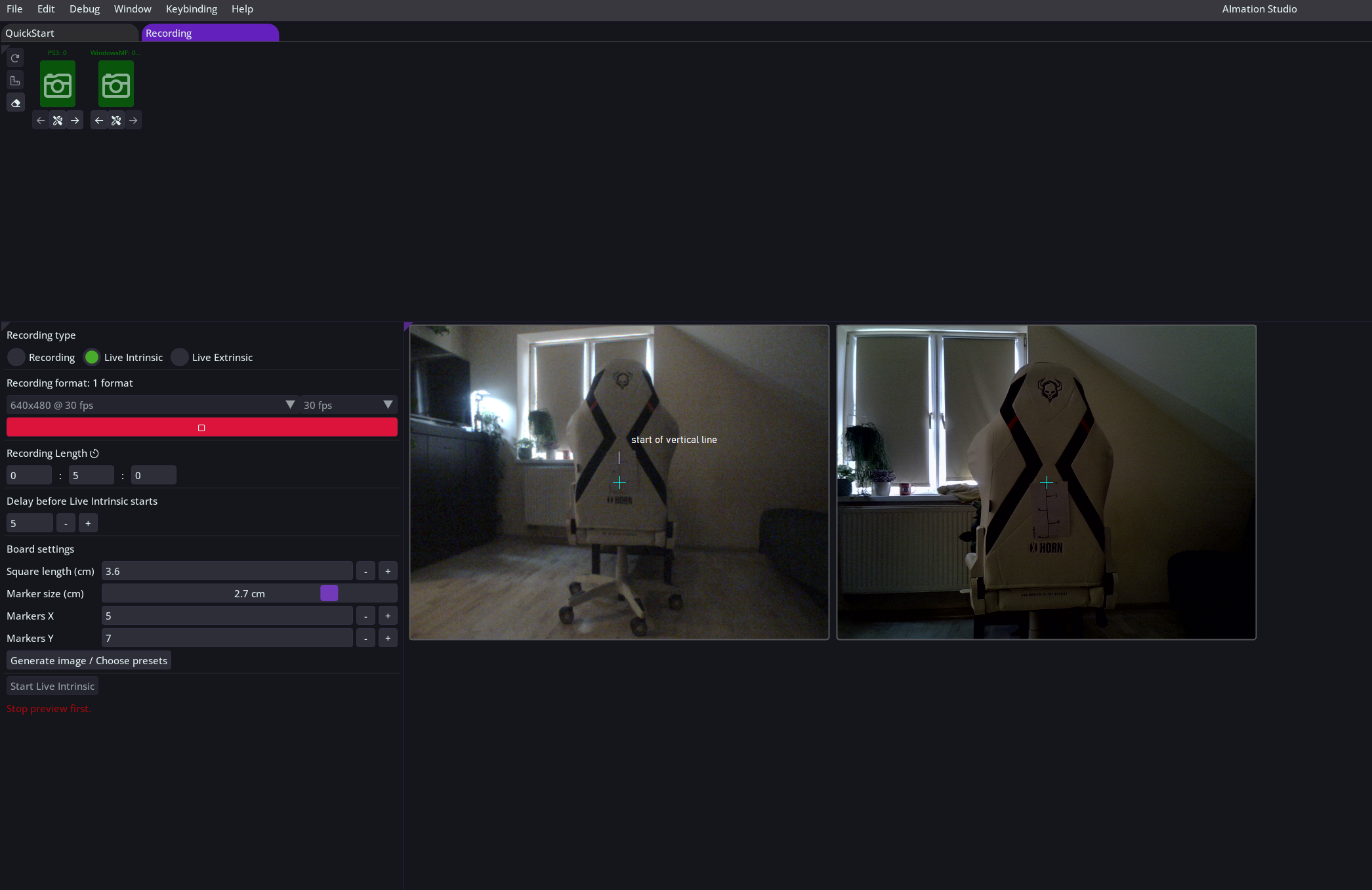
Image below shows view from behind the cameras with each measurement marked.
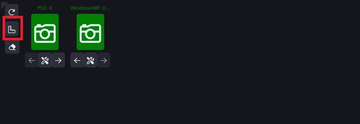
In this final step, we will input measurements into calibration UI, which can be accessed by pressing the ruler icon next to camera order.
This will open Extrinsic Manager window where we will input all taken measurements, note that currently set resolution will be copied in this step, so make sure the same one is currently set.
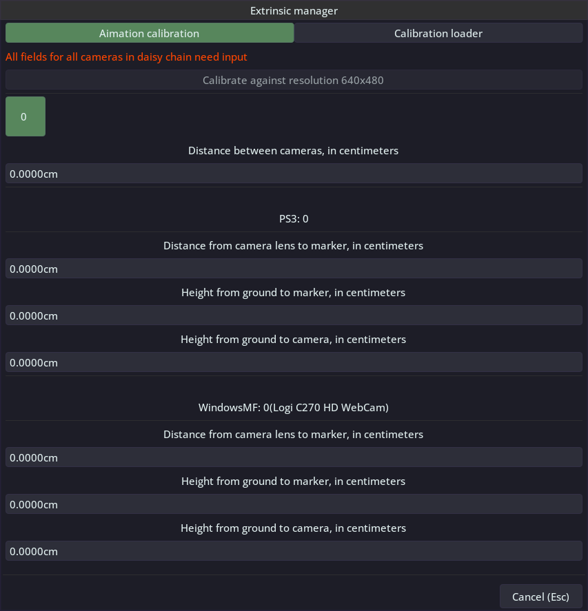
Distance between cameras: camera lens to be exact
Starting from the top, the green button with 0 in it indicates for which pair we are currently inputing data. Hover over it for additional data and press to switch to another pair, input data persists.
All inputs are in centimeters.
Fill in all fields for each pair. The 'Calibrate' button at the top will activate once all fields are completed. Pressing it will initiate the calibration using the provided inputs. After the process is complete, you will have the option to save the results under a specific name. It is recommended to choose a unique and distinguishable name, especially if you later plan to re-create the scenario.
Once saved you can navigate to Calibration Loader in the upper part of the window which will now contain newly created result.
More at Loading extrinsic calibrationor Your first multi-device recording
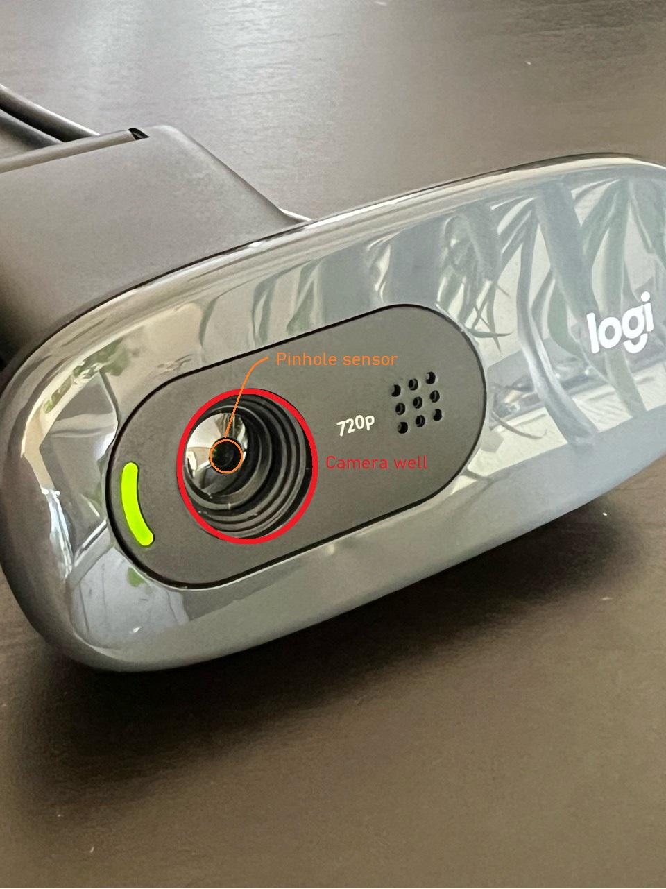
(*) Lens and camera well example
Camera well is where the sensor lies, marked with red circle on the image, we measure towards the center of this well without touching the device because even slight movements will invalidate our alignment.
Estimate the distance between center of the well and the sensor (marked green on the image), in this case we estimate it to be roughly 0.2mm. Add that value to your measurements ( e.g. distance to/from lens to point on vertical line )
